TSB151, TSB152 Shock Relay for Industrial Overload Protection
Unplanned downtime is the enemy of industrial efficiency. In manufacturing and processing environments, a single mechanical failure can cascade into hours of lost production and costly repairs. The most common culprit? Overload conditions. When a conveyor jams or a heavy load stalls a motor, the resulting mechanical shock can destroy drive components instantly.
While thermal overload relays have been a staple for protecting motors from overheating over time, they often react too slowly to sudden, massive spikes in current caused by mechanical jams. This is where specialized protection becomes critical. Industrial shock relays like the TSB151 and TSB152 are designed to bridge this gap, offering rapid response to shock loads that threaten the integrity of motors, power transmission systems, and the machinery itself.
In this guide, we will explore how TSB151 and TSB152 shock relays function, why they are essential for industrial safety, and how they integrate with systems utilizing roller chains, sprockets, and couplings.
What Is a Shock Relay in Industrial Applications?
A shock relay is an electronic device designed to monitor the current drawn by an electric motor. Its primary purpose is to detect sudden load increases—often referred to as “shock loads”—that occur when machinery encounters resistance beyond its design limits. Unlike standard fuses or thermal protection, which focus on heat generation and long-term overcurrent, a shock relay focuses on the immediate mechanical stress placed on the system.
In industrial applications, mechanical protection is just as vital as electrical safety. If a foreign object blocks a crushing machine, the motor will attempt to push through, drawing excessive current. Without intervention, this torque spike can snap shafts, break chains, or burn out the motor windings. A shock relay detects this current spike within milliseconds and trips the circuit, cutting power before catastrophic damage occurs.
Shock Relay vs. Thermal Overload Relay
It is important to distinguish between these two protective devices to ensure proper system design.
- Thermal Overload Relays: These operate based on the heating effect of current. They are excellent for preventing motor burnout caused by slight, prolonged overloads. However, their thermal inertia means they are slow to react to instant jams.
- Shock Relays (Electronic Shear Pins): These act as electronic limiters. They provide instantaneous protection against severe mechanical overloads. They are often used in conjunction with thermal relays to provide comprehensive protection: thermal relays for the motor’s health, and shock relays for the mechanical drive system’s integrity.
Understanding Industrial Overload Protection
Industrial systems face a constant battle against friction, inertia, and variable loads. Overload conditions generally fall into two categories: gradual and sudden. Gradual overloads might occur due to bearing wear or lack of lubrication. Sudden overloads, however, are violent events—a rock jamming a conveyor belt or a tool falling into a mixer.
The impact of these shock loads extends far beyond the motor. The kinetic energy stored in the moving parts has to go somewhere. When the output shaft stops abruptly, that energy is transferred backward through the transmission. This puts immense stress on:
- Chains and Belts: Rapid tension spikes can stretch or snap drive media.
- Sprockets and Pulleys: Teeth can strip or shear off under sudden torque.
- Couplings: Flexible elements may tear, or rigid connections may shatter.
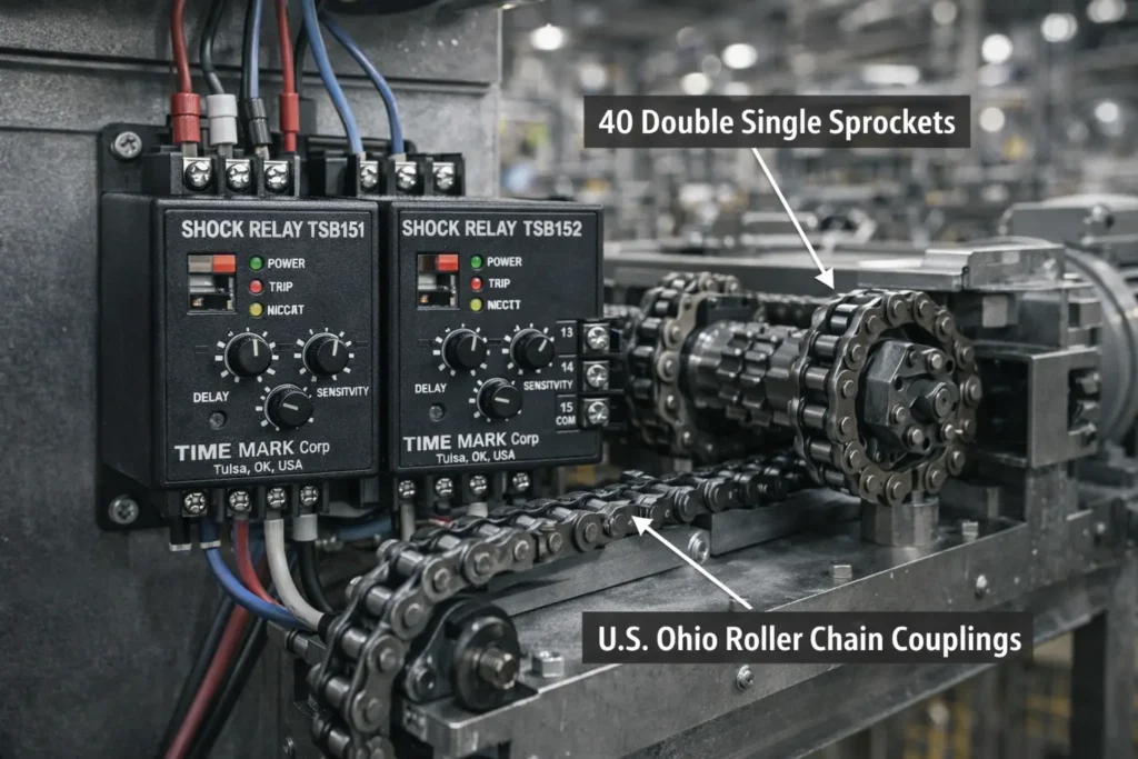
Protecting these components is essential for maintaining the lifespan of the equipment. For instance, in a chain-driven system, the interaction between the chain and the 40 Double Single Sprockets is a critical wear point. If a jam occurs, the shock load is transmitted directly to the sprocket teeth. A properly installed shock relay prevents the torque from reaching breaking point, saving the sprocket from expensive replacement.
Overview of TSB151 and TSB152 Shock Relays
The TSB151 and TSB152 series are engineered specifically for the rigors of the industrial environment. They are built to withstand the electrical noise, vibration, and temperature fluctuations common in factories and processing plants.
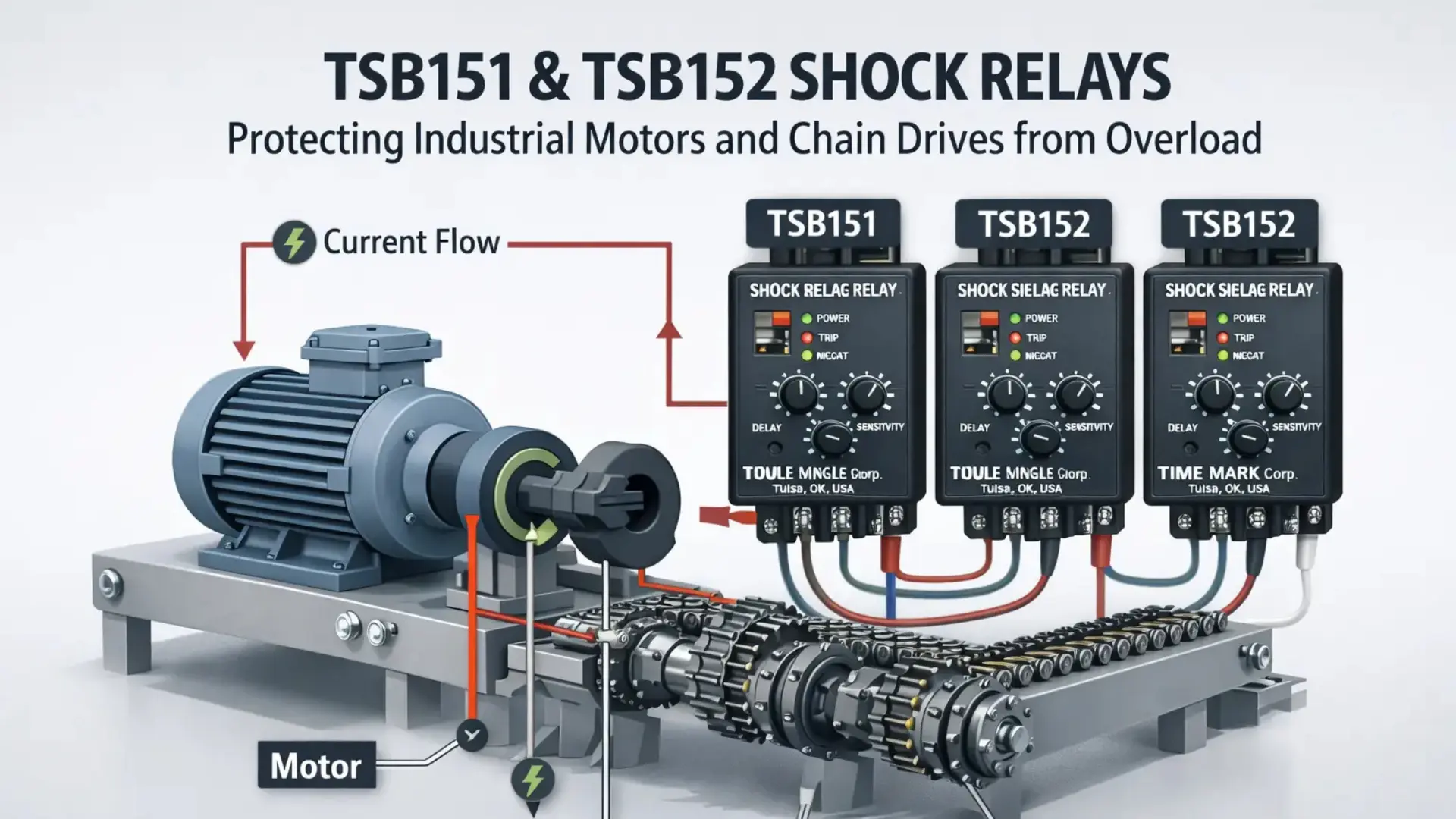
These devices offer a robust solution for detecting overcurrent caused by mechanical locking or overload. They function by continuously comparing the motor’s operating current against a preset threshold. If the current exceeds this limit for a specific duration (shock time), the internal relay trips, changing the state of the output contacts. This signal can be used to stop the motor contactor or trigger an alarm system.
Key Features
- Solid-State Reliability: With no moving parts in the sensing circuit, these relays offer consistent performance over thousands of cycles.
- Adjustable Settings: Operators can fine-tune the trip current and the shock time to suit specific application needs, preventing nuisance tripping during normal startup surges.
- Compact Design: Designed for easy integration into crowded control panels and motor control centers (MCCs).
TSB151 vs TSB152: Choosing the Right Shock Relay
While both models serve the same fundamental purpose—protecting equipment from shock loads—there are nuances in their specifications that dictate which unit is best for a given scenario.
TSB151
The TSB151 is often the go-to for standard industrial applications. It typically covers a specific current range suitable for small to medium-sized motors. It is designed for general-purpose protection where standard sensitivity is required.
- Operating Current: Generally suited for lower to mid-range amperage.
- Application: Ideal for small conveyors, packaging machinery, and light assembly lines.
TSB152
The TSB152 usually offers a broader or higher current range, or enhanced features for more demanding environments. It may include additional CTs (Current Transformers) or different wiring configurations to handle larger loads.
- Operating Current: Capable of handling higher power motors, often with external CTs.
- Application: Heavy-duty crushers, large wastewater pumps, and heavy material handling.
Selecting the correct model involves analyzing the full load amperage (FLA) of the motor and the nature of the load. If the machinery experiences frequent, high-inertia starts, the TSB152’s configuration options might provide better stability.
Working Principle of TSB151 & TSB152
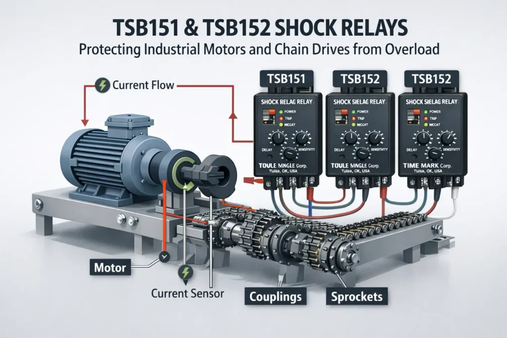
The operation of these relays revolves around accurate current sensing. The motor leads (typically two of the three phases) pass through the relay’s built-in current transformers. This induces a voltage proportional to the current flow.
The Trip Mechanism
- Start-Time Delay: When a motor starts, inrush current can be 6 to 10 times higher than the running current. If the relay reacted instantly, it would trip every time the machine started. The TSB series includes a “Start Time” setting that disables the trip function for a set period (e.g., 0.2 to 10 seconds) allowing the motor to reach operating speed.
- Shock Time (Reaction Time): Once the motor is running, the relay enters monitoring mode. If a jam occurs, current spikes. The “Shock Time” setting determines how long the overcurrent must persist before tripping. This prevents trips caused by momentary, harmless load fluctuations.
- Reset: After a trip, the relay must be reset. This can be manual (requiring an operator to press a button) or automatic (resetting after a cooldown period), depending on safety protocols.
Industrial Applications of TSB151 and TSB152
These shock relays are versatile components found across almost every sector of heavy industry.
Conveyors and Material Handling
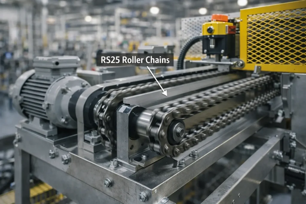
In automated warehousing and mining, conveyors move tons of material. If a pallet breaks or a rock gets stuck, the belt stalls. A shock relay stops the drive motor instantly, preventing the belt from burning through due to friction against the drive drum. This is particularly crucial for systems utilizing RS25 Roller Chains. These precise chains are often used in smaller, intricate conveyor drives. A sudden shock load can stretch the pitch of the chain, ruining its ability to mesh with sprockets and necessitating a complete replacement.
Pumps and Compressors
Pumps dealing with viscous fluids or sludge (like in wastewater treatment) are prone to clogging. A “dead-head” condition or a solid object entering the impeller causes a rapid spike in torque. TSB151/152 relays protect the pump shaft and seals from the destructive forces of a locked rotor.
Machinery Using Chain Drives
Any machine driven by chain requires protection. Chain drives are efficient but unforgiving of shock loads. When a drive halts unexpectedly, the tension on the tight side of the chain skyrockets. This can damage the chain, the sprockets, and the shaft couplings connecting the motor to the gearbox. By using a shock relay, you protect components like U.S. Ohio Roller Chain Couplings, which rely on the integrity of the chain to transmit torque. Saving a coupling is far cheaper than replacing a gearbox shaft.
Benefits of Using TSB151 & TSB152 in Industry
Integrating these devices into your motor control strategy offers tangible ROI.
- Prevents Catastrophic Failure: The primary benefit is the prevention of severe damage. Replacing a shear pin is easy; replacing a bent motor shaft is not. The shock relay acts as an electronic shear pin that never needs physical replacement—just a reset.
- Reduces Downtime: Mechanical repairs take time. Parts must be ordered, and maintenance crews dispatched. An electrical trip can be investigated and reset in minutes, getting production back online faster.
- Improves Equipment Lifespan: By eliminating the stress of prolonged overload conditions, the mechanical wear on bearings, gear teeth, and couplings is significantly reduced.
- Operational Reliability: Consistent protection means operators can run machines closer to their optimal capacity without fear of unseen damage accumulating over time.
Installation and Wiring Guidelines
Proper installation is critical for the TSB151 and TSB152 to function correctly. These units are typically mounted on a DIN rail or bolted directly to the back panel of a control cabinet.
Wiring Overview
- Power Supply: Ensure the control voltage matches the relay specifications (e.g., 110V, 220V, or 24V DC).
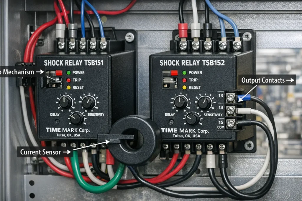
- Current Sensing: Pass two of the three motor phase wires through the sensing apertures (CT windows) on the relay. Direction does not matter, but they must pass through clearly without putting stress on the relay casing.
- Output Contacts: Wire the normally closed (NC) contact in series with the motor starter coil. When the relay trips, this contact opens, de-energizing the starter and stopping the motor. The normally open (NO) contact can be wired to a PLC input or a red fault light on the panel door.
Safety Note: Always disconnect and lock out power before installing or servicing these relays. High voltages inside industrial control panels present a severe arc flash and shock hazard.
Maintenance and Troubleshooting
While solid-state devices require little maintenance, the system as a whole should be part of a routine inspection schedule.
Routine Inspection
- Visual Check: Inspect the relay for signs of overheating or physical damage. Ensure wires passing through the CTs are not chafing.
- Testing: Periodic testing simulates an overload. Many units have a “Test” button. Pressing this should trip the relay and stop the motor, verifying that the control wiring is intact.
Troubleshooting Common Issues
- Nuisance Tripping on Start: If the relay trips every time the machine starts, the “Start Time” delay may be too short. Increase the delay setting slightly to cover the duration of the inrush current.
- No Trip During Jam: If the machine jams but the relay doesn’t trip, the “Trip Current” setting may be set too high. Dial it down to a level closer to the actual running current, or check if the “Shock Time” is too long.
- Recalibration: If motor loads change (e.g., after a gearbox service or oil change), the running current may shift. Recalibrate the trip point to match the new baseline.
Compliance and Industrial Safety Standards
In the modern industrial landscape, compliance with safety standards (such as IEC, NEMA, or UL) is non-negotiable. Overload protection is a mandated requirement for motor circuits to prevent fire hazards and equipment explosions.
Shock relays contribute to a safer work environment by minimizing the violent failures of mechanical systems. A snapping chain or exploding coupling poses a significant risk to nearby personnel. By keeping the drive system within its mechanical limits, TSB151 and TSB152 relays help facilities meet safety obligations regarding machine guarding and risk mitigation. Proper integration into the safety circuit ensures that a mechanical fault results in a safe, controlled stop.
Why Choose Our TSB151 & TSB152 Shock Relays
When your production line is on the line, you need components you can trust. Our TSB151 and TSB152 shock relays are built for the most demanding industrial environments, offering precision, durability, and peace of mind.
- Industrial-Grade Build: Tested for high vibration and harsh electrical environments.
- Proven Reliability: Trusted by maintenance managers to protect critical assets from conveyors to crushers.
- Expert Support: Our team understands the difference between electrical overload and mechanical shock, helping you select the perfect protection for your specific drive system.
Don’t wait for a breakdown to upgrade your protection. Ensure your motors, chains, and couplings survive the shock.